
Table of Contents
Fleet EV Charging Solutions: Enterprise Infrastructure & Energy Management
Transitioning commercial transport, logistics, municipal transit, and field service operations to electric vehicles requires moving from traditional liquid fuel setups to sophisticated electrical systems. Modern fleet EV charging solutions rely on connected infrastructure designed around specific operational duty cycles, route logistics, utility tariffs, and long-term fleet growth.
Unlike public consumer networks, commercial fleet charging revolves around predictability and operational efficiency. Vehicle downtime must be minimized, charging must align with shift schedules, and energy costs must be managed to maintain low operational expenses.
Fleet electrification relies on three core operational models:
- Centralized Depot Charging: Vehicles return to a company-owned facility for overnight AC or fast DC charging.
- Take-Home / Distributed Charging: Drivers park take-home company vehicles at their personal residences, utilizing residential Level 2 chargers linked to automated enterprise reimbursement software.
- En-Route / Opportunity Fast Charging: High-power DC fast charging or Megawatt Charging Systems (MCS) located along transit corridors or logistics hubs to extend vehicle range during working shifts.
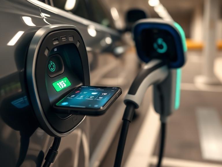
Strategic Fleet Infrastructure Classification
Matching charging power levels to vehicle classes and dwell times ensures cost-effective hardware installation while meeting daily mileage requirements.
       Level 2 High-Output AC          Depot DC Fast Charging (DCFC)       Megawatt Charging System (MCS)
     [ 11.5 kW - 19.2 kW Output ]       [ 50 kW - 180 kW Output ]          [ 375 kW - 1,200 kW+ Output ]
     +---------------------------+      +---------------------------+      +------------------------------+
     | Dwell Time: 6 to 10 Hours |      | Dwell Time: 1 to 3 Hours  |      | Dwell Time: 15 to 45 Minutes |
     | Vans, Sedans, Service EVs |      | Box Trucks, School Buses  |      | Heavy Semi-Trucks, Regional  |
     +---------------------------+      +---------------------------+      +------------------------------+
| Fleet Vehicle Category | Typical Battery Capacity | Recommended Charger Type | Power Output Range | Primary Use Case Profile |
| Light-Duty Fleet (Sedans, Light Vans) | 50 kWh – 85 kWh | High-Output Level 2 AC | 7.2 kW – 19.2 kW | Overnight depot parking or take-home residential |
| Medium-Duty Fleet (Box Trucks, Buses) | 100 kWh – 250 kWh | Medium DC Fast Charger (DCFC) | 50 kW – 180 kW | Between-shift turnover or overnight depot fast charging |
| Heavy-Duty Fleet (Class 8 Semis) | 300 kWh – 800+ kWh | High-Power DCFC / MCS | 250 kW – 1,200 kW+ | Opportunity fast charging, en-route, port drayage |
1. High-Output Level 2 AC Depot Solutions
For light-duty vehicles (such as municipal fleets, service sedans, and last-mile delivery vans) that dwell for 8 to 12 hours overnight, 208V/240V high-output Level 2 chargers (up to 19.2 kW / 80A) offer a reliable, cost-effective infrastructure solution.
2. Commercial Depot DC Fast Chargers
When fleets operate multiple shifts or rely on large batteries (such as medium-duty box trucks or school buses), Level 2 charging cannot restore full capacity during short dwell windows. Compact, dual-port DC fast cabinets (50 kW to 180 kW) supply direct current directly to traction batteries, restoring 80% charge in 1 to 2 hours.
3. Megawatt Charging Systems (MCS) for Heavy-Duty Freight
Heavy-duty logistics, Class 8 long-haul trucks, and port drayage vehicles require high energy delivery. Emerging Megawatt Charging System (MCS) solutions deliver up to 3.75 MW of power at up to 1,250 volts and 3,000 amps, giving long-haul heavy trucks 200+ miles of additional range during mandatory 30-minute driver rest breaks.
Grid Architecture, Site Planning & Power Optimization
Planning a commercial fleet charging site requires evaluating facility power supplies and managing potential peak demand charges.
                  TYPICAL FLEET DEPOT POWER ARCHITECTURE SCHEMATIC
+-------------------------------------------------------------------------------+
| Utility Primary Feed (13.8 kV / 4160V 3-Phase Service)                        |
+-------------------------------------------------------------------------------+
                                        |
                                        v
+-------------------------------------------------------------------------------+
| Dedicated Step-Down Transformer (480V 3-Phase, 2500 kVA)                      |
+-------------------------------------------------------------------------------+
                                        |
                                        v
+-------------------------------------------------------------------------------+
| Main Fleet Switchgear & Smart Distribution Panel (3000A Bus Rating)           |
+-------------------------------------------------------------------------------+
                                        |
             +--------------------------+--------------------------+
             |                                                     |
             v                                                     v
+----------------------------------+                     +----------------------+
| BESS Energy Storage Cabinet      |                     | Solar Canopy Array   |
| (1 MW / 2 MWh Battery Buffer)    |                     | (300 kW PV Generation)|
+----------------------------------+                     +----------------------+
             |                                                     |
             +--------------------------+--------------------------+
                                        |
                                        v
+-------------------------------------------------------------------------------+
| Centralized Power Conversion Cabinets & Dynamic Distribution Units            |
+-------------------------------------------------------------------------------+
                                        |
         +------------------------------+------------------------------+
         |                              |                              |
         v                              v                              v
+------------------+           +------------------+           +------------------+
| Overhead Overhead|           | Overhead Overhead|           | Overhead Overhead|
| Reel Dispenser 1 |           | Reel Dispenser 2 |           | Reel Dispenser 3 |
+------------------+           +------------------+           +------------------+
Managing Utility Peak Demand Charges
Commercial electric utilities assess demand charges based on the highest 15-minute power peak (in kW) recorded during a billing cycle. Unmanaged, simultaneous fast charging across a fleet can trigger high demand charges, reducing operating savings.
$$\text{Monthly Peak Demand Charge (\$)} = \left( \max_{t} [P_{\text{Charging}}(t) + P_{\text{Facility}}(t)] \right) \times \text{Tariff Rate Standard}\ (\$/\text{kW})$$
To control these costs, operators install Automated Load Management (ALM) software. ALM automatically adjusts power delivery across connected stalls according to departure times, electricity pricing, and site power limits.
               UNMANAGED VS. SMART LOAD MANAGED FLEET CHARGING
  Power (kW)
    ^
 800|     [Unmanaged Peak Load - High Demand Charges]
    |         /---\
 600|        /     \
    |       /       \
 400|------/---------\-------------------------------- [Facility Grid Cap]
    |     |           |       [Smart ALM Load-Managed Curve - Low Cost]
 200|_____|___________|___________________________________________________
    +---------------------------------------------------------------------> Time
    6 PM     8 PM     10 PM     12 AM    2 AM     4 AM     6 AM     8 AM
On-Site Solar PV and Battery Energy Storage Systems (BESS)
Integrating localized solar PV arrays with Battery Energy Storage Systems (BESS) builds site power resilience. The battery buffer charges during off-peak times or from solar output, discharging during peak charging windows to reduce total grid draw.
Hardware Connectors and Dynamic Power Distribution
Selecting durable hardware and modular power systems ensures reliable long-term fleet depot operations.
    NACS / SAE J3400 Plug                CCS Combo 1 Plug              Megawatt MCS Connector
+----------------------------+     +----------------------------+     +----------------------------+
| Compact Single-Handle      |     | Dual-Pin Lower DC Section  |     | Triangular High-Amp Pins   |
| Up to 1000V DC / 500A      |     | Up to 1000V DC / 500A      |     | Up to 1250V DC / 3000A     |
+----------------------------+     +----------------------------+     +----------------------------+
Dynamic Power Allocation Architecture
Modern fleet depots use centralized power cabinets paired with satellite dispensers instead of individual standalone chargers.
       CENTRAL POWER CABINET WITH DYNAMIC DISPENSER MATRIX
+-----------------------------------------------------------------+
| Centralized Power Module Cabinet (e.g., 360 kW Matrix)          |
| [ Module 1: 60kW ] [ Module 2: 60kW ] [ Module 3: 60kW ]        |
| [ Module 4: 60kW ] [ Module 5: 60kW ] [ Module 6: 60kW ]        |
+-----------------------------------------------------------------+
                                |
        +-----------------------+-----------------------+
        | Dynamic Power Matrix Switchboard              |
        +-----------------------+-----------------------+
            |                   |                   |
            v                   v                   v
      +-----------+       +-----------+       +-----------+
      | Dispenser |       | Dispenser |       | Dispenser |
      |  Stall 1  |       |  Stall 2  |       |  Stall 3  |
      | (180 kW)  |       | (120 kW)  |       |  (60 kW)  |
      +-----------+       +-----------+       +-----------+
When a depleted vehicle plugs in, the central matrix allocates multiple 60 kW power modules to its dispenser for fast charging. As the battery tops off and its charge rate slows, the system automatically redirects idle power modules to other vehicles needing energy.
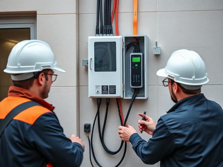
Software Orchestration: Telematics, OCPP & V2G Systems
A successful fleet electrification project relies on a connected software ecosystem linking vehicle telematics, route scheduling, charging hardware, and utility grids.
+---------------------------------------------------------------------------------------+
|                    ENTERPRISE FLEET SOFTWARE & TELEMETRY FLOW                         |
+---------------------------------------------------------------------------------------+
|                                                                                       |
|  [Vehicle Telematics] ---> CAN bus State of Charge (SoC), Battery Temperature, Odometers |
|                                                                                       |
|  [Fleet Management]  ---> Shift Schedules, Departure Times, Route Distance Demands    |
|                                                                                       |
|                                         |                                             |
|                                         v                                             |
|  [Smart Load Engine] ---> Optimizes kW Delivery, Utility Tariffs, Peak Shaving       |
|                                                                                       |
|                                         |                                             |
|                                         v                                             |
|  [OCPP 2.0.1 Cloud]  ---> Controls Hardware Charging Power Profiles & Sessions        |
|                                                                                       |
+---------------------------------------------------------------------------------------+
Telematics Integration
Fleet telematics systems provide real-time updates on vehicle State of Charge (SoC), battery temperature, location, and daily energy consumption. Software uses this data to prioritize charging schedules automatically based on each vehicle’s next assigned departure time and route distance.
+------------------------------------------------------------------------------------+
|               EXAMPLE TELEMATICS-DRIVEN DISPATCH CHARGING QUEUE                    |
+------------------------------------------------------------------------------------+
| Vehicle ID  | Current SoC | Target SoC | Scheduled Departure | Priority Status     |
| Total Fleet | Level       | Level      | Window              | Ranking             |
+-------------+-------------+------------+---------------------+---------------------+
| Van #104    | 12%         | 90%        | 05:00 AM            | 1 - Immediate Max kW|
| Bus #202    | 45%         | 100%       | 06:30 AM            | 2 - Medium kW Load  |
| Truck #309  | 68%         | 80%        | 09:00 AM            | 3 - Deferred Night  |
+------------------------------------------------------------------------------------+
Vehicle-to-Grid (V2G) and Vehicle-to-Building (V2B) Implementation
Parked fleet vehicles with bidirectional chargers can operate as a distributed energy resource. During peak electricity rate windows, V2G software discharges power from connected fleet batteries back into company buildings or the local utility grid, generating utility revenue while keeping vehicles ready for their morning shifts.
Depot Layout, Cable Management & Civil Engineering
Designing a commercial depot layout requires balancing vehicle turning radiuses, accessibility, cable safety, and physical hardware protection.
                    OVERHEAD REEL DISPENSER DEPOT LAYOUT
+-----------------------------------------------------------------------------------+
|                                                                                   |
|  +----------------------+      +---------------------+     +-------------------+  |
|  | Overhead Gantries    |      | Retractable Spring  |     | Concrete Safety   |  |
|  | Supporting Cable     | ---> | Cable Reels         | --> | Curb Island       |  |
|  | Run Distribution     |      | (Zero Ground Drop)  |     | Protection        |  |
|  +----------------------+      +---------------------+     +-------------------+  |
|                                                                                   |
|     ========================================================================      |
|     | Vehicle Drive-In Bay  |  Heavy Truck Parking Stall  | Clearance 16 Ft |      |
|     ========================================================================      |
|                                                                                   |
+-----------------------------------------------------------------------------------+
Overhead Cable Retraction Systems
Ground-mounted charging cables in busy commercial depots are susceptible to damage from being run over by heavy vehicles. Overhead gantry systems with spring-loaded cable retractors keep cables elevated and off the ground, extending cable life, protecting connectors, and eliminating tripping hazards.
Financial Models: Total Cost of Ownership (TCO) & Energy-as-a-Service
Transitioning a commercial fleet to electric vehicles shifts financial spending from ongoing fuel operational costs (OpEx) to upfront infrastructure capital investments (CapEx).
                     FLEET CAPEX VS OPEX COST STRUCTURE SHIFT
  Internal Combustion Engine (ICE) Fleet             Electric Vehicle (EV) Fleet
+-----------------------------------------+     +-----------------------------------------+
| Initial Vehicle Purchase (Lower CapEx)  |     | Initial Vehicle & Depot (Higher CapEx)  |
| High Diesel/Gasoline Fuel (High OpEx)   |     | Low Electricity Charges (Lower OpEx)    |
| Frequent Engine/Brake Repairs (OpEx)    |     | Reduced Brake/Drivetrain Service (OpEx) |
+-----------------------------------------+     +-----------------------------------------+
TCO Comparison: ICE vs. EV Commercial Fleet
While EV trucks and charging infrastructure require higher upfront capital, operational savings in fuel and reduced maintenance produce a favorable Total Cost of Ownership (TCO) over the vehicle’s lifespan.
      5-YEAR TOTAL COST OF OWNERSHIP (TCO) PER VEHICLE (CLASS 6 BOX TRUCK)
  $ Cost
 200k +-------------------------------------------------------------------------+
      |  [ICE Diesel Truck - Total: $185,000]                                   |
 150k |  +--------------------+--------------------+--------------------+       |
      |  | Purchase: $85,000  | Diesel: $70,000   | Service: $30,000  |       |
 100k |  +--------------------+--------------------+--------------------+       |
      |  [Electric Truck + Depot Share - Total: $125,000]                       |
  50k |  +--------------------+--------------------+--------------------+       |
      |  | Purchase: $105,000 | Energy: $15,000   | Service: $5,000    |       |
    0 +--+--------------------+--------------------+--------------------+-------+
Energy-as-a-Service (EaaS) Financial Models
To reduce initial capital requirements, many enterprise fleets use Energy-as-a-Service (EaaS) financing. Under an EaaS model, a third-party partner designs, installs, owns, and maintains the charging infrastructure, transformer upgrades, and software systems. The fleet operator pays a single predictable monthly fee based on kilowatt-hours consumed, treating infrastructure as a manageable operating expense.
Step-by-Step Fleet Electrification Roadmap
Implementing enterprise fleet charging requires systematic planning across engineering, utility, and operations teams.
1.Fleet Duty Cycle Analysis & Power Assessment:Months 1–3.
Collect vehicle telematics data to analyze daily mileage, dwell time windows, route profile requirements, and facility electrical capacity across all depot locations.
2.Utility Interconnection & Infrastructure Design:Months 4–6.
Submit formal load capacity inquiries to local utilities, design 30%/60%/100% electrical site plans, select OCPP-compliant hardware, and submit permit applications.
3.Civil Construction & Utility Transformer Upgrades:Months 7–12.
Trench conduit lines, pour reinforced concrete dispenser pads, install step-down transformers, mount switchgear, and set power conversion cabinets.
4.Telematics, Software & Automated Load Integration:Months 13–14.
Bind hardware to the cloud management backend, integrate vehicle telematics feeds, establish dynamic load profiles, and test automated charging protocols.
5.System Commissioning & Driver Training:Months 15+.
Perform high-voltage system testing, train fleet drivers and depot staff on connection protocols, and launch full electric fleet operations.
Frequently Asked Questions (FAQs)
1. How do enterprise fleet EV charging solutions differ from public charging infrastructure?
Fleet EV charging solutions are engineered for predictable operational schedules, duty cycles, and energy management. Unlike public chargers built for ad-hoc access, fleet infrastructure integrates directly with fleet telematics, depot dispatch schedules, route software, and automated load-balancing systems to eliminate utility demand charges.
2. What is the typical infrastructure cost to electrify a commercial fleet depot?
Depot electrification costs range from $50,000 to $100,000 for small Level 2 delivery fleets, and from $500,000 to over $3,000,000 for high-power DC fast-charging depots serving medium- and heavy-duty trucks. Costs cover switchgear, step-down transformers, trenching, power cabinets, software licenses, and utility interconnection upgrades.
3. What is Automated Load Management (ALM) in fleet EV charging?
Automated Load Management (ALM) is an intelligent software control layer that dynamically manages power distribution across connected chargers. It ensures total power draw stays below site grid caps, prioritizes vehicles based on upcoming departure times, and helps prevent expensive utility peak demand charges.
4. What charging hardware power levels are needed for light, medium, and heavy-duty fleets?
Light-duty fleets (delivery vans, corporate sedans) usually rely on 19.2 kW Level 2 AC chargers for overnight depot parking. Medium-duty trucks (box trucks, school buses) require 50 kW to 180 kW DC fast chargers. Heavy-duty semi-trucks need 250 kW to 350+ kW DC fast chargers or Megawatt Charging Systems (MCS).
5. How does vehicle telematics integrate with fleet EV charging software?
Telematics software communicates wirelessly with fleet vehicles to monitor real-time battery State of Charge (SoC), operational health, daily range requirements, and route assignments. This data feeds directly into charging management software to prioritize charging for vehicles scheduled for early departure.
6. What is Vehicle-to-Grid (V2G) and Vehicle-to-Building (V2B) for fleet operators?
V2G and V2B are bidirectional charging capabilities that allow parked fleet batteries to discharge stored power back into the utility grid or local facility during peak tariff periods. This helps offset facility electrical costs and provides emergency backup power during outages.
7. How can fleet operators avoid high utility demand charges?
Fleet operators reduce demand charges by scheduling charging during off-peak hours, using software-driven load shedding, staggering charge start times, and installing local Battery Energy Storage Systems (BESS) to supply power during peak demand periods.
8. What is the typical timeline for deploying a dedicated fleet EV charging depot?
Deploying a dedicated fleet depot typically takes 8 to 24 months. While hardware mounting takes just weeks, the schedule is dominated by utility grid interconnection studies, transformer provisioning, municipal permitting, and high-voltage civil engineering.
9. What connector standards apply to commercial fleet electric vehicles?
North American commercial fleets primarily use NACS (SAE J3400) and CCS Combo 1 for light and medium-duty vehicles. Heavy-duty transport fleets are adopting Megawatt Charging Systems (MCS), which deliver up to 3.75 MW of power through specialized high-current connectors.
10. What is the difference between depot charging, take-home charging, and en-route charging?
Depot charging powers vehicles at a centralized corporate facility overnight or between shifts. Take-home charging provides employee residences with networked Level 2 chargers for home charging with automated expense reimbursement. En-route charging uses public DC fast chargers to extend vehicle range along long routes.
11. What is Energy-as-a-Service (EaaS) for fleet electrification?
Energy-as-a-Service (EaaS) is a subscription financial model where a third-party partner designs, funds, builds, owns, and maintains the fleet charging infrastructure. The fleet operator pays a predictable monthly operating fee based on energy consumed, avoiding upfront capital costs.
12. Why is OCPP protocol compliance critical for fleet charging infrastructure?
OCPP (Open Charge Point Protocol) enables open communication between hardware chargers and backend management software. It prevents vendor lock-in, allowing operators to change software providers or add hardware from different manufacturers without replacing existing physical equipment.
13. How does dynamic power sharing work in a multi-dispenser fleet depot?
Dynamic power sharing routes power from centralized power conversion cabinets to individual dispensers based on real-time vehicle needs. As vehicles finish charging, power automatically redirects to vehicles that still need energy, speeding up overall fleet charge times without increasing total grid capacity.
14. What maintenance is required for commercial fleet EV charging stations?
Maintenance includes inspecting liquid-cooled cable assemblies, cleaning air filters on power cabinets, updating firmware, testing ground-fault systems, inspecting physical bollards, and monitoring network communication units.
15. How do extreme ambient temperatures impact fleet EV charging operations?
Cold weather increases internal battery resistance and requires extra power for pre-conditioning, while heat requires additional thermal cooling. Fleet management software adjusts charging power profiles to protect battery life and pre-conditions vehicle cabins while still plugged into depot power.


Leave a Comment